How to ensure optimal functioning of a power supply

Five key considerations for power engineers
INTRODUCTION
Power supplies (AC/DC) are indispensable for the operation of electronic devices. This crucial component converts electrical energy from sources like the power grid (230VAC) into a usable voltage for the device, such as 24VDC for a programmable logic controller (PLC). In other situations, a DC voltage from a car battery (12VDC) needs to be converted to another value, such as 48VDC, using a converter (DC/DC), a voltage used in the latest cars for electric windows. A DC/DC converter can also provide a stable voltage to prevent a battery voltage from collapsing under increasing load or decreasing temperature. Additionally, a DC/DC converter can provide galvanic isolation to protect sensitive and expensive electronics at the output from surges like peak voltages at the input.
Without power supplies or converters, there would be no LED lighting, trains wouldn't run, coffee machines wouldn't grind beans, and we couldn't listen to the radio or watch television. However, improper use of power supplies can also cause significant problems. If the design of a device does not consider factors like inrush currents, peak currents, leakage currents, or heat development in the housing, there is a risk that an application will not meet the applicable standards or will not function at all.
Failing power supplies often cause malfunctions. According to a study by Zerto, a specialist in disaster recovery, over 30 percent of hardware failures in IT environments are caused by power supplies. Data loss, productivity loss, and ultimately revenue loss can be the direct result of such a failure.
In many cases, malfunctions due to failing power supplies can be prevented by considering the power supply requirements during the design phase of a device. What should engineers consider? In this white paper, we list five important considerations and provide tips that contribute to flawless operation.
TYPES OF POWER SUPPLIES
Most engineers will be familiar with the operation of the power supply and the pros and cons of different types of power supplies. To understand the challenges in the field of power supplies, it can be helpful to go back to the basics. How have power supplies evolved over time? And what types can we broadly distinguish?
LINEAR POWER SUPPLIES
In linear power supplies, a transformer adjusts the high input voltage to a workable, lower output voltage. This is followed by a rectifier bridge with diodes and smoothing. Finally, the output voltage is regulated or stabilized by a control circuit, such as a shunt regulator that absorbs the voltage difference.
Linear power supplies are large and heavy because they operate at the mains frequency. They also have low efficiency, producing a lot of heat. Due to these disadvantages, linear power supplies are increasingly less used. The advantage of this type of power supply is its ability to deliver a very stable and precise voltage. Therefore, linear power supplies are still attractive for use in measuring instruments, for example.
SWITCHING POWER SUPPLIES
In a Switched-Mode Power Supply (SMPS), a transistor receives a control signal at a very high frequency, 100 kHz or even much more. This is the switching frequency. The period is very short, and during this period, the transistor is brought into conduction for a longer or shorter time. In other words, the transistor receives a PWM (Pulse Width Modulation) control signal with a varying duty cycle (the ratio of on-time to the period). For example, if the voltage threatens to collapse under increasing load, the transistor will receive a PWM signal with a larger duty cycle. This keeps the transistor in conduction longer, allowing more energy to be transferred from the input to the output. As a result, the output voltage will immediately rise to the required value, such as 24VDC, and remain stable under varying loads.
The main advantage of switching power supplies is that, thanks to the switching frequency, which is much higher than that of a linear power supply, the capacitances or inductances can be much smaller to achieve the same effect, the same reactance. The required components and the transformer of a switching power supply are therefore much more compact than those of a linear power supply, while the efficiency is much higher. However, there are also disadvantages. The high switching frequency still causes switching losses.
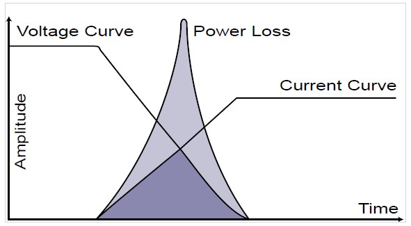 |
Figure 1. Power Loss
Additionally, electrical disturbances – the so-called Electro Magnetic Interference (EMI) – are inevitable with this type of power supply. Larger peak voltages and currents also cause stress and therefore wear on the components. By replacing the diodes with MOSFETs that are switched on and off in pairs, the switching losses can be limited. This is called synchronous rectification.
RESONANT CONVERTERS
Just before the transformer, a resonant tank is placed in which sinusoidal voltages and currents are generated. This enables 'soft switching'. Switching on or off can then occur at moments when the voltage or current is zero. This is also known as Zero Voltage Switching (ZVS) or Zero Current Switching (ZCS). The losses in these converters are minimal, ideally even zero, especially when working with SIC MOSFETs. Switching on and off now occurs at a fixed duty cycle of 50 percent (the on-time is equal to the off-time) but at a varying frequency depending on the direction in which the output voltage needs to be adjusted. The disadvantage is that the circuit of a resonant converter is much more complex than that of a switching power supply. Because there is no fixed switching frequency, the filter is also more complex.Just before the transformer, a resonant tank is placed in which sinusoidal voltages and currents are generated. This enables 'soft switching'. Switching on or off can then occur at moments when the voltage or current is zero. This is also known as Zero Voltage Switching (ZVS) or Zero Current Switching (ZCS). The losses in these converters are minimal, ideally even zero, especially when working with SIC MOSFETs. Switching on and off now occurs at a fixed duty cycle of 50 percent (the on-time is equal to the off-time) but at a varying frequency depending on the direction in which the output voltage needs to be adjusted. The disadvantage is that the circuit of a resonant converter is much more complex than that of a switching power supply. Because there is no fixed switching frequency, the filter is also more complex.
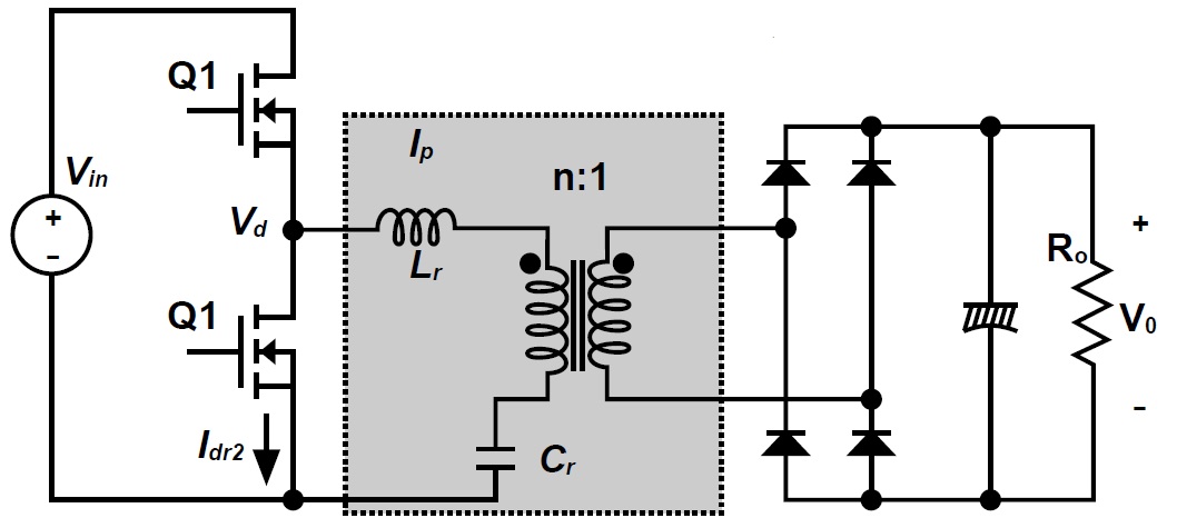 |
Figure 2. Operation of a resonant converter
CONSIDERATIONS
Most electronic devices today use switching power supplies, often in combination with PWM. The resonant converter is more expensive and complex. This type of converter is still used for high-end applications. Especially when minimizing switching losses is important, the resonant converter – optionally with SIC MOSFETs – can be a logical choice.
In all cases, the power supply is an important consideration during the design of a device, whether it is an industrial machine or lighting. What should a power supply meet, considering factors such as housing, environmental factors, and applicable standards? In the following chapters, we will discuss:
- Electro Magnetic Interference
- Inrush and peak currents
- Power density and thermal management
- Protection against high current draw
- Certifications
ELECTRO MAGNETIC INTERFERENCE
The power drawn from the mains is the ratio of the output power to the product of the efficiency and the power factor. This power factor is, in turn, the product of two power factors: the power factor due to a phase shift between voltage and current on the one hand (for example, by starting heavy motors every morning that represent a large inductive load) and the power factor resulting from a distortion of the current drawn from the mains.
This latter form of 'pollution' on the mains – or Electro Magnetic Interference (EMI) – is what we deal with in switching power supplies.
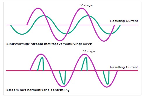 |
Figure 3. Cos Phi
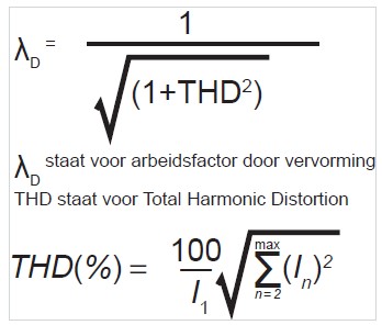 |
Figure 4. Power factor due to distortion
The result is that there is too much reactive power. As a result, electricity suppliers have to provide more power than necessary and install thicker cables to transport the reactive power, which does not contribute to useful power. In Europe, EN 61000-3-2 aims to tackle the 'polluters' of the power grid by enforcing the use of power supplies with Power Factor Correction (PFC). PFC ensures that both even and odd harmonics remain below a certain level. This makes the current drawn from the grid resemble a sine wave more closely, bringing the distortion factor closer to 1 and limiting reactive power.
Compliance with the standard is mandatory in the EU when a device draws between 75W and 1000W of power from the grid. A large group of devices falls within this category, from computers and refrigerators to televisions, cash registers, and surveillance cameras. For lighting, the lower limit is even 25W, as often dozens of drivers are connected to one group. Non-compliance with EN 61000-3-2 can have far-reaching consequences for a manufacturer of equipment. In more and more sectors, customers include PFC in their specifications. No power supply with PFC applied? Then the respective product is not accepted. There are two ways to adjust the power factor and thus reduce reactive power:
PASSIVE PFC
A delay coil is placed at the input. This causes the current to lag and resemble a sine wave more closely. Harmonics are thus reduced, as well as reactive power.
ACTIVE PFC
An electrical circuit with transistors and diodes ensures that a nearly perfect sine wave is drawn from the grid. The power factor is still slightly dependent on the input voltage and load but is almost equal to 1. A power supply with active PFC comes with a higher price tag.
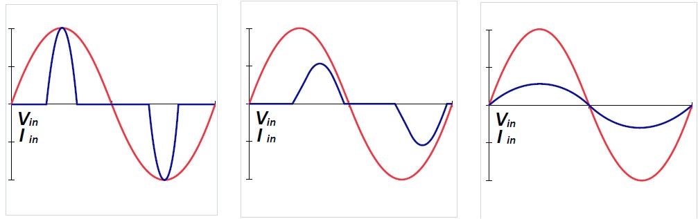 |
Figures 5-7. Input current without (L), with passive (M), and active (R) PFC
INRUSH AND PEAK CURRENTS
When switching on a switching power supply, short and high inrush currents can occur due to empty capacitors, which can reach up to 50A or even more. These inrush currents last a fraction of a second and therefore do not pose dangerous situations. Warming up the wires is not possible in such a short time. However, if the design does not account for inrush currents, there is a risk that the circuit breakers will fail and the application will be without power. This can be prevented in several ways.
SLOW CIRCUIT BREAKERS
By using 'slow circuit breakers'. For example, a circuit breaker with a 'B characteristic' can handle 3 to 5 times the nominal current and is therefore suitable for common household appliances. Circuit breakers with a 'C characteristic' can handle 5 to 10 times the nominal current and are recommended for medium inrush currents or when multiple power supplies are connected to the same group. Circuit breakers with a 'D characteristic' are mainly intended for use in industrial environments.
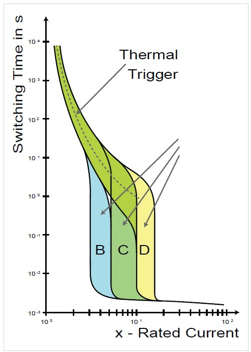 |
Figure 8. Slow circuit breakers
PASSIVE INRUSH CURRENT LIMITATION (ICL)
An electrical resistor (NTC) absorbs the inrush current. This is a cheap solution that is relatively easy to implement. The disadvantage is that at higher power levels, the power losses become too large if the resistor is always in series with the load. Moreover, this Passive Inrush Current Limitation is less suitable when the power supply is continuously switched on and off. After several switches, the resistor is warmed up and no longer provides protection.
ACTIVE INRUSH CURRENT LIMITATION
A fixed resistor is used, which is now temperature-independent. The resistor is bridged by a switching semiconductor. When a current peak occurs – at startup but also in operation – the semiconductor will open, so the current is limited by the resistor. When the peak is over, the semiconductor closes to avoid useless dissipation in the resistor. This solution is obviously more expensive.
A peak in power consumption can also have other causes than switching on the device and can last longer than a fraction of a second. For example, a coffee machine grinding beans needs higher 'current' for a few seconds. In such cases, using a power supply with a 'peak power feature' is worth considering. There are power supplies on the market designed to deliver 10A but can handle 18A. However, care must be taken that the duty cycle of the peak current does not exceed a certain value and the average current does not exceed the nominal.
POWER DENSITY AND THERMAL MANAGEMENT
High power levels come in increasingly smaller housings. For example, there are converters on the market that deliver 250W in a housing no larger than a 'half brick', with an input range of 16-160VDC. Compact housings make it more difficult to dissipate power losses in the form of heat, affecting the lifespan of components. A commonly used rule – based on the Arrhenius equation – is that if the temperature rises by 10 degrees, the lifespan of electronic components is halved. Too high a temperature also causes the power supply to go into protection. Good thermal management is therefore crucial. During the design phase, heat development must be considered to choose the right power supply.
IMPORTANT QUESTIONS DURING THE DESIGN PROCESS:
- What is the temperature 1 to 3 centimeters above the power supply?
- What is the ambient temperature? Will the device be in Norway or Dubai? The final location has a significant impact on thermal management.
- What does the housing look like? Does it provide sufficient opportunities to dissipate heat? In a waterproof IP67 housing, the temperature rises even further.
- Is there a metal wall to screw the power supply against?
- Are there opportunities to build in a fan? What forced cooling can be considered?
- In what position is the power supply mounted, e.g., horizontal or vertical?
PROTECTION AGAINST HIGH CURRENT DRAW
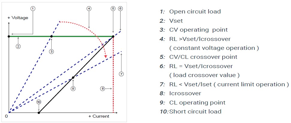
If a motor 'sputters' at startup, the correct protection against high current draw is often not chosen. With 'Foldback Current Limiting', the power supply is often unable to deliver the required current – unless the power supply is oversized – causing the overcurrent protection to activate and the power supply to shut down. The motor tries to start again, and the same thing happens. The motor sputters but does not start. The repeated startup causes a ticking sound typical of a 'hiccup characteristic'.
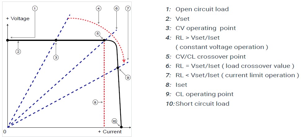
Placing a larger power supply could be a solution but is not always desirable, for example, due to space constraints or a limited budget. 'Constant Current Limiting' is a better option in such situations. After exceeding the maximum current, the output voltage briefly drops, but the required current is delivered, and the voltage immediately recovers to the required value, such as 24VDC.
Figure 9. Foldback Current Limiting
Figure 10. Constant Current Limiting |
CERTIFICATIONS
An important question during the selection of a power supply is: to which countries will the device be exported? If there is export to the United States, the power supply must meet the safety and EMC requirements of the Underwriters Laboratories. Is UL Recognized sufficient, or is UL Listed needed? Or are there plans for export to Germany and China? Then the TÜV, EAC, and CCC certifications are applicable, respectively.
Certification for a national mark is an expensive affair. The costs for a single process can quickly amount to $10,000. If a product is exported to, for example, 10 countries, it is cheaper to go through a certification process for a Certified Body (CB) mark. Such a process costs about the same as a single process, but a CB mark is often internationally accepted.
If the certifications of the different countries are explicitly needed, a CB report still provides a cost advantage. When submitting a CB report, the costs per country are often reduced from $10,000 to about $3,000. These $3,000 are purely the administrative costs that the various certification bodies charge for issuing their mark after evaluating the CB report.
CONCLUSION
All electrical devices need one or more power supplies or converters. They cannot do without them. However, the selection of the right power supply is very important. A power supply that is not optimally matched to the design of the product inevitably causes power problems.
These power problems can have far-reaching consequences. A device that pollutes the power grid too severely may not be accepted by customers. If insufficient consideration is given to inrush and peak currents, a device, machine, or application may not function at all. These problems can be prevented by carefully considering what the right power supply is for the application early in the design phase.