Choosing the right Thermal Interface Materials

How do you choose the right Themal Interface Materials (a Laird WHITEPAPER)
Designers know that electronics dissipate heat and that certain components can reach unacceptably high temperatures. In some application areas, such as 5G telecom infrastructure, modern data center infrastructure, and automotive control systems, excessive heat can shut down a system, forcing designers to come up with new cooling solutions. More of these systems are packaged in enclosures with challenging form factors, making the implementation of large heat sinks and fans very difficult or unfeasible. Thermal interface materials are one of the tools designers can use to dissipate heat from critical components, especially when forced airflow is not available.
As more electrical designers face challenges related to form factor and heat dissipation, they may not be familiar with the range of thermal interface material options on the market, or how to select the right mix of materials to solve specific design challenges. Laird Performance Materials offers multiple thermal interface material options that can help designers solve complex thermal challenges. These solutions are applicable for use in automotive, telecom, data center, and power conversion systems, as well as many other markets. In this whitepaper, we will explore the range of thermal interface materials on the market, as well as some of the design goals that need to be achieved when selecting these materials.
Why designers need thermal interface materials
Thermal interface materials are intended to provide uniform thermal contact between two adjoining surfaces, usually a component and its heat sink. In the past, system designers would typically use a fan, heat sink, or both as an all-encompassing solution for most cooling problems with specific components. This was because most heat was generated in bulky power supplies or large CPUs, both of which were large enough to accommodate such cooling measures. Even in modern systems where forced airflow over a heat sink is present, the problem remains to quickly dissipate heat from a hot component to the heat sink. Thermal interface materials offer a solution by filling gaps between machined surfaces, ensuring uniform contact and high heat transfer efficiency. The same idea applies when the enclosure acts as the heat sink.
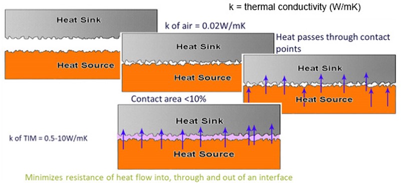 |
Figure 1. The problem solved by the Thermal Interface Material
Thermal interface materials are sometimes generically called "gap fillers" because they fill small air gaps between machined surfaces, as shown in Figure 1. By adding a material to fill gaps between machined surfaces, a path to a heat sink with low thermal resistance is created. With the right thermal interface material, heat sink, and path for natural or forced convection, the thermal resistance from the target component to the environment can be reduced.
The challenge for many designers is comparing thermal interface materials for use in connecting components to heat sinks, components to enclosure elements, or a board to an enclosure.
Types of thermal interface materials and connections
Thermal gap fillers are available in solid and liquid forms, allowing them to be incorporated into various processes while meeting diverse product performance requirements. The gap filler materials described below are intended for interfacing between a hot component and a chassis, or between a hot component and a heat sink.
Liquid gap fillers:
These materials are better known as thermal pastes, thermal putty, or sometimes thermal grease, with some manufacturers using these terms interchangeably. These materials are applied directly to a component and can be applied very quickly with automated processing. Liquid gap fillers typically consist of a resin system mixed with ceramic, metal, or metal oxide fillers, giving these materials their competitively high thermal conductivity. Liquid gap fillers are ideal for applications requiring high deformability at low pressures and low constant stresses. Cure-in-place options may also be considered for applications requiring enhanced reliability.
Thermal greases and phase change materials:
Other types of thermal interface materials include thermally conductive greases and phase change materials (PCMs). These differ from gap fillers in that they are generally used in applications with a thin bond line, typically 50 microns or less, where the adjoining surfaces are relatively flat. These types of materials do not fill a significant gap within the application. The primary function of these greases and phase change materials TIMs is to wet the surfaces of the heat source and heat sink to closely bond those two surfaces together. Generally, these materials are used in applications with constant applied pressure. Typically, greases flow and wet surfaces at room temperature, while phase change materials need to heat the device to flow and wet the surfaces.
High thermal conductivity PCB laminates:
When some PCB designers think of high thermal conductivity laminates, they tend to lean towards metal core or ceramic constructions. Newer advanced resin systems can offer higher thermal conductivity than standard FR4 laminates, but without the manufacturing issues of those alternative stackups. When used as a thermal interface material, these laminates can provide high heat transfer to an enclosure through direct conduction, or through another thermal interface material such as a solid thermal pad. Possible application areas include automotive power systems, backplanes, and industrial electronics.
Thermal pads:
Thermal pads, sometimes referred to as gap fillers, are a class of TIMs that "fill a large gap" between heat-generating and heat-dissipating surfaces. Often, thermal pads are used to cover multiple heat sources within an application and connect them to a common heat sink. A gap filler is expected to be sufficiently compliant to accommodate multiple module heights and tolerances within applications without generating excessive pressure levels within the system. These materials are typically supplied as die-cut parts between release films, on a roll, or in sheets. These materials are available in various compositions:
- Silicone- or paraffin wax-based filled materials that offer properties such as excellent surface wetting, high thermal stability, flexibility, and physiological inertness.
- Electrically insulating materials for use when ESD and insulation concerns are present.
- Graphite-based materials that offer high overall conductivity, particularly in-plane conductivity for use on larger components.
Specifying thermal interface materials
There are several material specifications that apply to thermal interface materials. The thermal conductivity of the material or the thermal resistance of the delivered product is a primary material property to consider, as this value can be used as a design target in simulations or some basic calculations. Many products require consideration of electrical and mechanical properties for use in their desired application.
These include:
- Dielectric strength and resistance: These are important for insulating thermal interface materials that will be used in high-voltage systems.
- Young's modulus: Some materials can provide a damping effect against vibrations, so mechanical properties should be considered when selecting materials.
- Temperature stability: Thermal interface materials must be reliable over a wide temperature range to ensure reliable thermal properties and prevent premature degradation.
- Dielectric constant: This is important for thermal pads that will be attached to a PCB, as the presence of a dielectric can alter the impedance of high-frequency transmission lines. The dielectric constant can also affect radiated EMI from a heat sink.
In addition to material properties, designers should consider automated assembly processes and the ease with which certain solutions can be integrated into a PCBA or enclosure during manufacturing. The above list of thermal interface materials comes in solid and liquid forms, giving designers some flexibility to choose the material that works best for their components, application, and assembly process.
Designing with thermal interface materials: An example
Because heat sinks and active cooling designs can involve many simulations, it is easy to assume the same applies to the use of thermal interface materials. In reality, design calculations for a system with a heat sink and a thermal interface material are quite simple and follow some basic analogies from circuit analysis. The central idea is to calculate the thermal resistance of the stacked component + interface + heat sink system and compare it to a component + air + heat sink system. By considering the relative thermal conductivities of an air gap interface, one can calculate the expected reduction in thermal resistance to the environment for a component with an attached thermal interface material and heat sink.
The system with a heat sink, component, and interface in between can generally be treated as a layered system with 1-D heat transfer. By using the bulk conduction relationship for layered materials, the thermal resistance of a system with air can be compared to a system containing the thermal interface material. The thermal resistances of each system are defined in Figure 2.
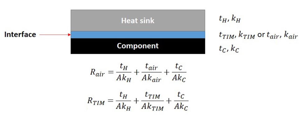 |
Figure 2. Thermal resistance
By subtracting the two thermal resistances, one can obtain the following relationship for the expected change in thermal resistance to the environment by adding the thermal interface material:
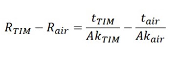 |
Figure 3. Thermal Interface Material
Typical TIM: air thickness ratios in the above system range from 10:1 to 1000:1, depending on the surface roughness of the machined heat sink and the attachment surface on the component. By comparing with a material with a thermal pad of 0.5 mm with a thermal conductivity of 3.5 W/(m.K), one finds that the expected reduction in thermal resistance to the environment for the lower component is approximately -3.81 °C/W for an integrated circuit of 5 mm × 5 mm.
This is a rough estimate, but it illustrates how various factors in a component and its heat sink affect heat transfer and a possible change in thermal resistance to the environment for the target component. This leaves a designer with three key points to consider when selecting a thermal interface material for a heat sink attachment:
- Thermal conductivity: Using a material with higher thermal conductivity reduces the overall thermal resistance of the TIM.
- TIM thickness: Using a thinner material will provide lower thermal resistance.
- Application area: Using a larger area will result in lower thermal resistance.